Troubleshooting flow measurement instability in chlor-alkali electrolysis systems under high EMI, pressure fluctuation, conductive brine mist, and thermal stress. Learn how shielding optimization, grounding redesign, vibration isolation, and adaptive signal processing improved chlorine and caustic soda flow accuracy from ±15% to ±0.8% in a high-current industrial environment.
Overcoming High-Pressure Interference in Chlor-Alkali Production with Customized Flow Meter Solutions
In chlor-alkali production, flow measurement problems are rarely caused by the meter alone.
At one chlor-alkali facility, operators had been dealing with unstable readings on both caustic soda and wet chlorine lines for several months. The issue became more noticeable whenever the electrolysis load increased or process pressure fluctuated during startup cycles.
The original instrumentation worked reasonably well under steady conditions, but once the electrolyzers moved into higher current operation, the flow signals began drifting unpredictably.
Maintenance teams initially suspected sensor damage. Later investigations showed the problem was more complicated.
Operating Conditions Behind the Instability
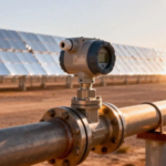
The flowmeters were installed close to electrolytic cells operating at 4–6 kA DC current. Under these conditions, several interference sources appeared simultaneously:
- strong electromagnetic interference from rectifier systems
- pressure pulsation during load changes
- conductive brine mist accumulating around cable connections
- elevated ambient temperatures near the cell room
On some lines, local temperatures approached 85°C during continuous operation.
Operators also noticed that measurement deviation became worse during pressure surges exceeding 4 MPa. In certain cases, the indicated flow fluctuated enough to affect stoichiometric balance inside the electrolyzer system.
For chlorine transfer lines, this created additional operational risk because unstable flow feedback complicated leak monitoring and dosing control.
Why Conventional Installation Methods Failed
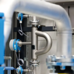
The original setup followed a fairly typical installation approach:
- standard shielded signal cables
- conventional transmitter grounding
- rigid mechanical mounting
- basic upstream straight pipe sections
Under normal industrial conditions, this arrangement would usually be acceptable.
Inside the electrolysis area, however, the environment behaved differently.
Large DC currents generated persistent electromagnetic noise around nearby instrumentation. At the same time, pressure pulsation from process fluctuations introduced mechanical vibration into the piping structure.
Over time, conductive brine deposits also started affecting terminal stability and signal quality.
The result was not one single failure point, but several small interference sources interacting together.
Modifications Made During the Upgrade
Instead of replacing the entire measurement system immediately, the engineering team focused first on isolating the dominant interference mechanisms.
Several changes were introduced step by step during scheduled maintenance windows.
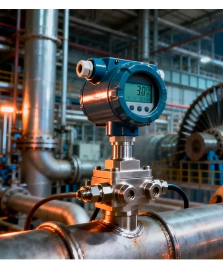
Additional Electromagnetic Shielding
The sensor assembly was redesigned with multi-layer shielding around the signal path.
This included:
- additional Faraday shielding layers
- mu-metal shielding near sensitive electronics
- improved cable isolation routing
After installation, electromagnetic interference measured near the transmitter dropped significantly compared with the original configuration.
Reducing Pressure-Induced Signal Disturbance
Pressure fluctuation was another major contributor.
Under rapid load changes, vibration from the process piping transferred directly into the sensor structure. To reduce this effect, vibration-isolated mounting supports were added between the flowmeter and skid structure.
This did not eliminate pulsation completely, but it reduced mechanical signal disturbance enough to stabilize the output.
Protection Against Conductive Brine Mist
One unexpected issue involved conductive residue accumulation near electrical connection points.
Although the instruments were technically sealed, long-term exposure to brine vapor gradually affected external signal stability.
To improve environmental resistance:
- connection protection was upgraded
- additional sealing barriers were installed
- PTFE-based protective surface coatings were applied on exposed areas
This reduced moisture-related signal drift during long operating cycles.
Signal Processing Adjustments
Hardware changes alone were not sufficient.
The plant also modified the signal processing logic used by the control system.
Several compensation functions were added, including:
- adaptive noise filtering
- pressure compensation under transient conditions
- temperature drift correction using embedded RTD feedback
FFT-based noise analysis was introduced to separate process flow variation from electrical interference patterns generated by nearby rectifier equipment.
Operators reported noticeably smoother flow trends after these adjustments.
Installation Changes That Made a Difference
Some of the most effective improvements were relatively simple installation changes.
Eliminating Ground Loop Problems
The original mounting arrangement unintentionally created multiple grounding paths between nearby equipment.
To reduce this issue, the upgraded installation used isolated mounting brackets with controlled grounding points.
This helped reduce unstable low-level signal fluctuation that had previously appeared during high-current operation.
Fiber-Optic Communication on Critical Chlorine Lines
On several chlorine transfer lines, conventional 4–20 mA wiring was replaced with fiber-optic signal transmission.
This reduced electrical interference pickup and improved signal stability in areas closest to the rectifier systems.
Results After the Upgrade
Performance improved gradually as each modification was implemented.
The largest improvement came after combining shielding upgrades with revised grounding architecture.
Before the project, some flow readings deviated by as much as ±15% during unstable operating conditions.
After optimization, measurement deviation was reduced to approximately ±0.8% under normal production loads.
Other operational improvements included:
| Parameter | Before Upgrade | After Upgrade |
|---|---|---|
| Measurement Deviation | ±15% | ±0.8% |
| Calibration Frequency | Weekly | Quarterly |
| Unplanned Downtime | 42 hrs/month | <2 hrs/month |
| Product Yield Variance | 8.7% | 1.2% |
Maintenance personnel also reported fewer troubleshooting interventions related to unstable transmitter signals.
Operational Impact on the Electrolysis Process
Improved measurement stability allowed operators to maintain tighter control over brine electrolysis conditions.
According to plant operating records:
- current efficiency improved by roughly 3%
- chlorine release incidents were significantly reduced
- chemical consumption became more stable
- maintenance planning became easier due to improved diagnostic consistency
The plant also reported lower maintenance spending after reducing repeated recalibration work and unscheduled instrumentation replacement.
Lessons From the Project
One important takeaway from this project was that severe measurement instability in chlor-alkali plants is often caused by multiple overlapping interference sources rather than a single instrument defect.
In high-current electrolysis environments, problems such as:
- EMI exposure
- grounding architecture
- vibration transfer
- conductive contamination
- temperature drift
can all influence measurement performance simultaneously.
Simply replacing the flowmeter without addressing installation conditions would likely not have solved the issue long term.